 |
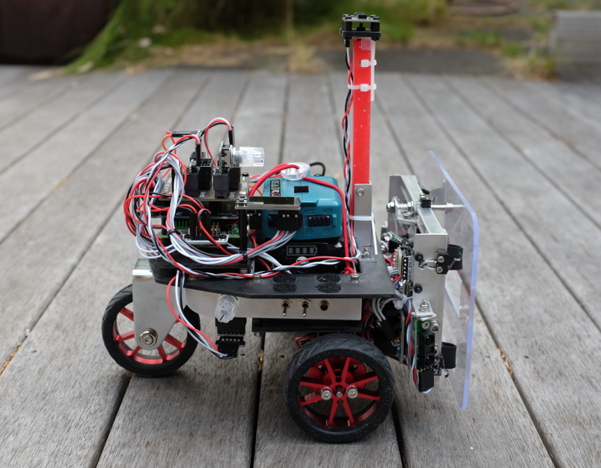
This page describes the KD01 robot, a 2 wheel (plus caster) differential drive robot. It shares the same software, chassis components, basic drive train, motor encoders and controllers as the KR01.
Description#
The KR01 robot is still under development, and as an experimental platform it is performing admirably.
 |
As it has no rotational steering like a car (i.e., its wheels are always facing perpendicular to the central axis of the robot), turning involves creating a difference in speed of either its port or starboard motors. Turning therefore requires wheel slippage. At an extreme, if the robot's wheels where so sticky that it couldn't slip over the surface of the ground, the robot couldn't turn at all. When the robot is on, say, a wooden floor, there is a noticeable shudder as its wheels alternately and unpredictably stick and un-stick from the surface, whereas on a dry wooden deck, on grass or dirt this wouldn't much of a problem.
So one limitation with its four wheel design — where the two motors on each side of the robot are wired in parallel to the motor controller — is that it has difficulty rotating in place when on any surface that provides significant friction for its silicon tires. When attempting to perform precise navigation on smooth indoor floors the KR01 is not really very well suited.
Hence the desire to build a differential drive robot.
...more later.
Available Media#
There's not much online yet about the robot but there is a blog entry and three YouTube videos:
- Differential Drive
 (NZPRG blog entry)
- KD01 Moth Behaviour
- KD01 Rotate in Place Test
- KD01 Rotate in Place (first try)
I2C Bus#
Things change all the time, but here's a sample of what's on the robot:
% i2cdetect -y 1
     0  1  2  3  4  5  6  7  8  9  a  b  c  d  e  f
00:          -- -- -- -- -- -- -- -- -- -- -- -- --
10: -- -- -- -- -- 15 -- -- 18 -- -- -- -- -- -- --
20: -- -- -- -- -- -- -- -- -- -- -- -- -- -- -- --
30: -- -- -- -- -- -- -- -- 38 -- -- -- -- -- -- --
40: -- -- -- -- -- -- -- -- 48 -- 4a -- -- -- -- --
50: -- -- -- -- -- -- -- -- -- -- -- -- -- -- -- --
60: -- -- -- -- -- -- -- -- -- -- -- -- -- -- -- --
70: -- -- -- -- 74 -- -- 77
- 0x15 : ThunderBorg motor controller
- 0x18 : RGB Encoder breakout
- 0x38 : HT0740 Switch (wired to cooling fan)
- 0x48 : ADS1015 AD converter
- 0x4A : BNO085 IMU
- 0x74 : starboard RGBMatrix5x5
- 0x77 : port RGBMatrix5x5
GPIO Pin Usage#
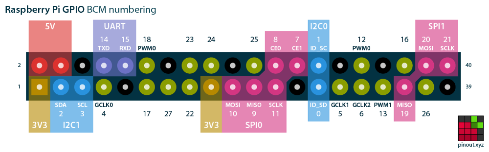 |
| PIN | PIN |
|---|---|
| 3V3 | +5V |
| 02: SDA (I2C) | +5V |
| 03: SCL (I2C) | GND |
| 04 | 14: TXD0 |
| GND | 15: RXD0 |
| 17: ENCODER A2 STBD (white) | 18: ENCODER B2 STBD (PCM_CLK) (violet) |
| 27: GPIO 27 (unused) | GND |
| 22: ENCODER A1 PORT (grey) | 23: ENCODER B1 PORT (blue) † |
| 3V3 † | 24: GPIO 24† Button B on 1.14" Mini Pi TFT Display |
| 10: MOSI† | GND † |
| 9: MISO† | 25: GPIO 25† |
| 11: SCLK† | 8: CE0† |
| GND | 7: CE1 |
| ID_SD | ID_SC |
| 5: ext clock (grey, from Itsy Bitsy) | GND |
| 6: rosd toggle switch (orange) | 12: PWM IRQ (TEMP) |
| 13: | GND |
| 19: | 16: Button A on 1.14" Mini Pi TFT Display (white/blue) |
| 26: (unused: conflict with SPI) | 20: Mast IR |
| GND | 21: |
‡ part of cable assembly connecting to Adafruit 1.14" Mini Pi TFT Display
Links#
- Differential Wheeled Robot on Wikipedia