This page contains some miscellaneous notes about wiring on the KR01 robot, included specifically so that the robot can be disassembled and reassembled without confusion about which wire goes where.
Overview#
The KR01 is currently using up most of the available GPIO pins, with a bunch being used by the Mini PiTFT display (which is optional). In the future we may offload the four encoder pins to the daughterboard containing the ItsyBitsy M4 Express. Most IO connections are planned to use the I2C bus.
We're not currently planning to use the PWM (pulse-width modulation), SPI, Serial (UART) or other GPIO features, just digital IO.
See: ThunderBorg Wiring
I2C Bus#
 ► i2cdetect -y 1
     0  1  2  3  4  5  6  7  8  9  a  b  c  d  e  f
00:          -- -- -- -- -- -- -- -- -- -- -- -- --
10: -- -- -- -- 14 15 -- -- -- -- -- -- -- -- -- --
20: -- -- -- -- -- -- -- -- 28 -- -- -- -- -- -- --
30: -- -- -- -- -- -- -- -- -- -- -- -- -- -- -- --
40: -- -- -- -- -- -- -- -- -- -- -- -- -- -- -- --
50: -- -- -- -- -- -- -- -- -- -- -- -- -- -- -- --
60: -- -- -- -- -- -- -- -- 68 -- -- -- -- -- -- --
70: -- -- -- -- 74 75 -- 77
- 0x14 : UltraBorg servo/ultrasonic controller
- 0x15 : ThunderBorg motor controller
- 0x28 : BNO055 9 DoF sensor
- 0x29 : VL531X ToF sensor
- 0x48 : ADS1015 AD converter
- 0x68 : PiJuice UPS
- 0x74 : starboard RGBMatrix5x5
- 0x75 : 11x7 LED Matrix
- 0x77 : port RGBMatrix5x5
GPIO Pin Usage#
| PIN | PIN |
|---|---|
| 3V3 | +5V |
| 02: SDA (I2C) | +5V |
| 03: SCL (I2C) | GND |
| 04 | 14: TXD0 STATUS LED |
| GND | 15: RXD0 PIR SENSOR |
| 17: ENCODER A2 STBD (white) | 18: ENCODER B2 STBD (PCM_CLK) (violet) |
| 27: GPIO 27 (unused) | GND |
| 22: ENCODER A1 PORT (grey) | 23: ENCODER B1 PORT (blue) † |
| 3V3 † | 24: GPIO 24† |
| 10: MOSI† | GND † |
| 9: MISO† | 25: GPIO 25† |
| 11: SCLK† | 8: CE0† |
| GND | 7: CE1 UPPER BUMPER |
| ID_SD | ID_SC |
| 5: PORT SIDE INFRARED | GND |
| 6: PORT INFRARED | 12: STBD SIDE INFRARED |
| 13: STBD BUMPER | GND |
| 19: CENTER BUMPER | 16: STBD INFRARED |
| 26: (unused: conflict with SPI) | 20: CNTR INFRARED | BUTTON |
| GND | 21: PORT BUMPER |

‡ part of cable assembly connecting to Adafruit 1.14" Mini Pi TFT Display
GPIO pin 20 is reserved for something, I can't remember.
 ► pinout
,--------------------------------.
| oooooooooooooooooooo J8     +====
| 1ooooooooooooooooooo        | USB
|                             +====
|      Pi Model 3B  V1.2         |
|      +----+                 +====
| |D|  |SoC |                 | USB
| |S|  |    |                 +====
| |I|  +----+                    |
|                   |C|     +======
|                   |S|     |   Net
| pwr        |HDMI| |I||A|  +======
`-| |--------|    |----|V|-------'

Revision           : a02082
SoC                : BCM2837
RAM                : 1024Mb
Storage            : MicroSD
USB ports          : 4 (excluding power)
Ethernet ports     : 1
Wi-fi              : True
Bluetooth          : True
Camera ports (CSI) : 1
Display ports (DSI): 1

J8:
   3V3  (1) (2)  5V
 GPIO2  (3) (4)  5V
 GPIO3  (5) (6)  GND
 GPIO4  (7) (8)  GPIO14
   GND  (9) (10) GPIO15
GPIO17 (11) (12) GPIO18
GPIO27 (13) (14) GND
GPIO22 (15) (16) GPIO23
   3V3 (17) (18) GPIO24
GPIO10 (19) (20) GND
 GPIO9 (21) (22) GPIO25
GPIO11 (23) (24) GPIO8
   GND (25) (26) GPIO7
 GPIO0 (27) (28) GPIO1
 GPIO5 (29) (30) GND
 GPIO6 (31) (32) GPIO12
GPIO13 (33) (34) GND
GPIO19 (35) (36) GPIO16
GPIO26 (37) (38) GPIO20
   GND (39) (40) GPIO21

For further information, please refer to https://pinout.xyz/
Port-Front Board (with BNO05 DoF and ItsyBitsy M4 Express)#
5 pin header:
| +5V | SCL | SDA | NA | GND |
Starboard-Aft Board (connections to below)#
|
|
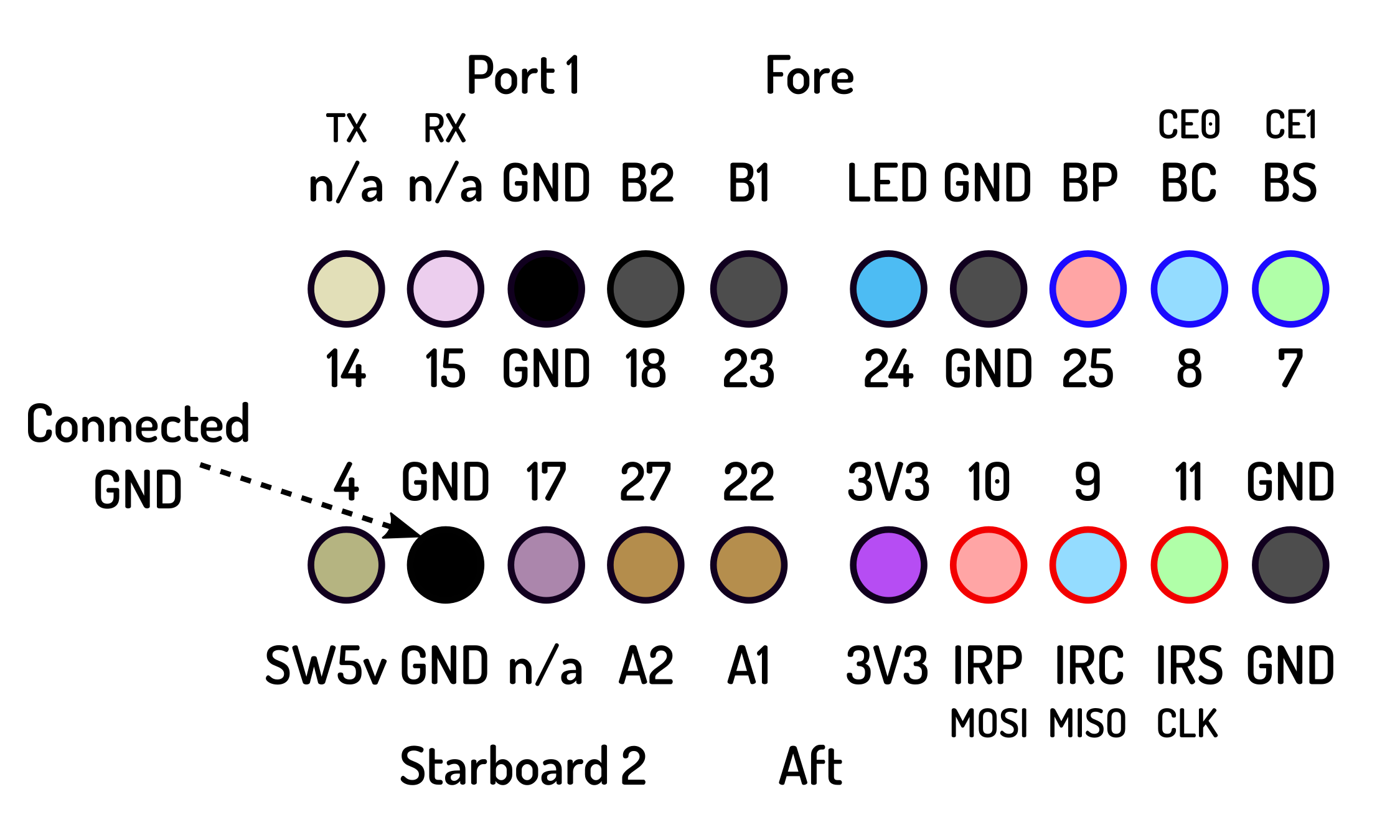
Mounted on the chassis, an Adafruit Perma Proto Bonnet serves to collect the various power and sensor connections into three connectors: one six pin connector comprising the first six GPIO pins (including 5V, 3.3V, Ground, SDA and SCL), and two ten (2x5) pin connectors. These are commonly called Dupont Connectors, bespoke cables made using dual row wire housings (see Small Dual Row Wire Housing Pack for DIY Jumper Cables).
The upper Starboard-Aft Board board provides two 10 pin connections to the lower board, which includes: the outputs from the bumpers (BP, BC and BS); infrared sensors (IRP, IRC and IRS); motor encoders (A1, A2, B1 and B2); indicator LED; and bypass/switched 5 volt sensor supply.
The color-coding of the jumper wires from the Starboard-Aft Board is as follows:
| Color | Connection | GPIO Pin |
|---|---|---|
| Purple | Port Bumper | 13 |
| Blue | Center Bumper | 19 |
| Green | Starboard Bumper | 26 |
| Color | Connection | GPIO Pin |
| Orange | Port Infrared | 12 |
| Yellow | Center Infrared | 6 |
| Green | Starboard Infrared | 5 |
| Color | Connection | GPIO Pin |
| Blue | Encoder A1 Port | 22 |
| Purple | Encoder A2 Starboard | 27 |
| Grey | Encoder B1 Port | 23 |
| White | Encoder B2 Starboard | 18 |
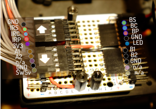
ItsyBitsy M4 Express & BNO055 Daughterboard#
 |
Earlier I'd experimented using a Perma-Proto board dedicated to holding an ItsyBitsy M4 Express and a BNO055 9-Axis Absolute Orientation sensor. The various connections to and from the daughterboard are shown in the above photo. The two columns of cyan and magenta-coloured pins are used to explode the 5V supply, which are used for the bumper and infrared sensors.
This board is currently not functional. The BNO055 is theoretically incompatible with the Raspberry Pi (the I2C bus speed needs to be slowed), so the ItsyBitsy was used to drive the BNO055 (and potentially poll other sensors). It seems the BNO055 is working okay with the Pi so lately I've just been connecting it directly.
More experiments are in order.