The SR04 robot was designed and built by David P. Anderson. It was David's fourth robot (hence the "04"), and was built sometime around 1998.
David has also suggested to me a Build Sequence which is a pretty good action plan for anyone building robots. As someone who's had a bit of trouble focusing on getting my robot going (there's just sooo much to learn!), his advice is greatly appreciated.
See also the links at bottom of this page.
Description:#
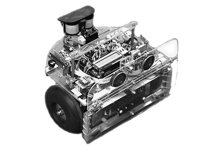 |
SR04 is a small mobile robot suitable for exploring human habitats unattended.
It is controlled by a Motorola HC6811 microprocessor running in an M.I.T. 6.270 CPU card, similar to the commercially available "Handy Board." Two 12-volt DC gear-head motors maneuver the robot in a dual-differential drive configuration, balanced by a non-driven tail wheel caster and powered by a 12 volt 2.2 amp-hour sealed lead acid battery. Sensory input is provided by (in order of priority): front bumper switches, IR collision avoidance, stereo sonar ranging, photo detectors, passive IR motion detection, and shaft-encoder odometry.
The SR04 was conceived around the following very loose design criteria:
- Survive in a wide range of (cluttered) human environments autonomously and continuously, without getting stuck.
- Provide a robust and reliable platform for developing navigation and behavior software.
- Be entertaining and aesthetic for the local human population.
Design#
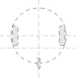 |
The design which has emerged is a small dual-differential drive platform with the geometry of an 11" circle. The drive wheels and tail caster sit on the perimeter of this circle, and thus it can rotate in its own space. This greatly simplifies software for maneuvering and collision avoidance.
CPUThe robot controller is a Motorola HC6811 microprocessor running in an M.I.T. 6.270 board. This card was developed for the introductory robotics course taught at M.I.T. It provides the HC6811 processor with 32k of battery-backed RAM, 32 eight-bit A/D channels, hardware 40kHz IR , 6 one-amp H-Bridge (L293) motor driver channels, an LCD readout, and some digital I/O ports for timer and output compare functions useful to robot builder-types.
Software |
The SR04 software exists as a collection of sensor routines and associated behaviors that are run concurrently by a round robn, non-preemptive multi-tasking scheduler. The structure is loosely based on Rodney Brooks' subsumption architecture as describe in Flynn's "Mobile Robots" book and more extensively on Brooks' home page (and elsewhere, run a web search on "subsumption").
Each sensor routine runs in turn in a 20 Hz sensor loop, and each sets a flag and some variables based on its own particular sensor input and state. An arbitration routine then picks the flag with the highest priority and passes it's variables along to the motor control sub-system. In this manner, sensors with higher priorities "subsume" the behaviors of lower priority sensors.
The priority scheme is based on the distance of the detecting event. Closer events have higher priority; more distant events have lower. The exact sequence is:
- 0 User
- 1 Bumpers
- 2 Rotation and Scanning
- 3 IR Collision Avoidance
- 4 Sonar Ranging
- 5 Photo Approach/Avoid
- 6 Motion Detector
- 7 Dead-reckoning
Thus the Sonar ranging layer can subsume the Photo, Motion, and Dead-reckoning layers when it detects an obstacle or clear pathway. It is in turn subsumed by the IR collision avoidance, and the Rotation and Scanning behavior subsume both. The Bumper layer holds the ultimate control. All other tasks save the User (that's me) must give way if the robot has actually run into something, until the bumper behavior declares the robot to be free from obstructions. This formalization is an extremely useful way to organize multiple and potentially competing sensor inputs.
Subsystems#
A. PID Controller#
A Proportional Integral Derivative (PID) algorithm is used to control the main drive motors and maneuver the robot. This useful and subtle control method consists of three subsystems:- Shaft encoders: Optical encoders attached directly to the motor shafts are used to accurately measure the speed of the motors (and by inference, the position of the robot).
- Pulse Width Modulation: Hardware timer interrupt generators in the HC6811 chip are used to generate two PWM sign
als that control the two L293 H-Bridges, which drive the main motors. - PID: The PID algorithm itself runs in the 20 Hz sensor loop. It samples the shaft encoder variables to determine the current motor speeds, compares these to the requested motor speeds, and adjusts the PWM values up or down to get sampled and requested values to match.
The inputs to the PID control sub-system are the global variables, velocity, and rotation. Velocity is a signed value that represents the speed at the center of the robot, and rotation is a signed value that represents the difference in velocity between the two wheels. The PID controller reads these values, calculates the proper encoder counts per second for each wheel, and attempts to slew the motors toward the requested values, 20 times per second.
This method of closed loop control has a number of advantages. The velocity of the robot becomes independent of battery voltage, as the PID controller will increase the pulse width to make up for the sagging supply. It is also independent of load, so the robot can move very slowly and still climb over objects and maintain constant speed on an incline. The ability to control the wheels smoothly over a wide speed range translates into the ability to precisely maneuver the robot. The PID controller also provides stability for dead-reckoning algorithms.
B. Odometry #
The encoder counts returned from the optical shaft encoders mounted on the drive motors are also used to track the position of the robot relative to its position when last reset. These are maintained as a set of global variables that are updated at the 20 Hz sensor loop rate.
X_position and Y_position are the Cartesian co-ordinates in inches, and Theta is the rotation of the 'bot around its center in degrees. These data provide the "sensor input" for the dead-reckoning behaviors.
C. Telemetry#
A pair of "Lynx" radio tx/rcv modules is used to implement a telemetry back channel. The robot transmits a continuous stream of 80 character ASCII packets at 2400 baud. These consist of odometer and sensor data, battery voltage, state flags, and so forth. These are received and piped directly to the computer screen, or tee'd off to a file for later perusal. The transmitter on the robot draws only about 10 ma and is useful out to around 50 feet, depending on the space.
web page.]
Links#
- SR04 Mobile Robot, project description by David P. Anderson (PDF version)
- SR04 Mobile Robot from the Newsletter of the Seattle Robotics Society
- Subsumption for hte SR04 and JBot Robots
David P. Anderson, 26 March 2007 - IMU Odometry: Tracking the robot's position in X,Y,theta with wheel encoders and wheel encoders plus gyroscope. Section II.B details the classical odometry algorithm for a two wheel differentially driven platform:
- The DPRG Outdoor Challenges: Navigation: Navigating to a waypoint target using the robot's location as collected by odometry as described in the previous paper
- Math Routines for the DPRG Outdoor Robot Challenge