The SR04 robot was designed and built by David P. Anderson. It was David's fourth robot (hence the "04"), and was built somewhere around 1998.
From David's description:
Design#
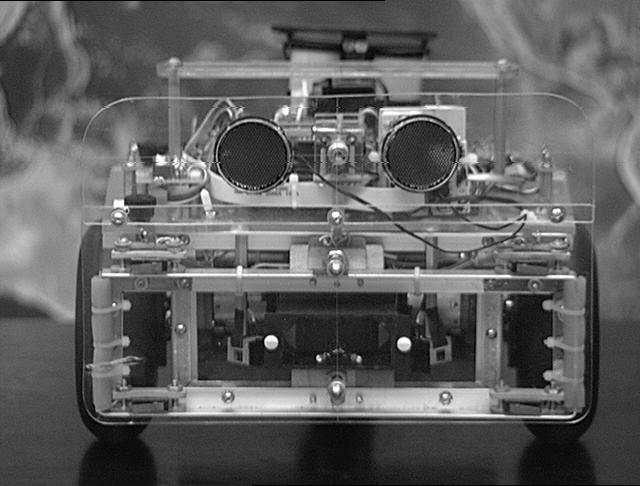 |
The design which has emerged is a small dual-differential drive platform with the geometry of an 11" circle. The drive wheels and tail caster sit on the perimeter of this circle, and thus it can rotate in its own space. This greatly simplifies software for maneuvering and collision avoidance.
CPUThe robot controller is a Motorola HC6811 microprocessor running in an M.I.T. 6.270 board. This card was developed for the introductory robotics course taught at M.I.T. It provides the HC6811 processor with 32k of battery-backed RAM, 32 eight-bit A/D channels, hardware 40khz IR , 6 one-amp H-Bridge (L293) motor driver channels, an LCD readout, and some digital I/O ports for timer and output compare functions useful to robot builder-types. Software
The SR04 software exists as a collection of sensor routines and associated behaviors that are run concurrently by a round robn, non-preemptive multi-tasking scheduler. The structure is loosely based on Rodney Brooks' subsumption architecture as describe in Flynn's "Mobile Robots" book and more extensively on Brooks' home page (and elsewhere, run a web search on "subsumption").
Each sensor routine runs in turn in a 20 Hz sensor loop, and each sets a flag and some variables based on its own particular sensor input and state. An arbitration routine then picks the flag with the highest priority and passes it's variables along to the motor control sub-system. In this manner, sensors with higher priorities "subsume" the behaviors of lower priority sensors.
The priority scheme is based on the distance of the detecting event. Closer events have higher priority; more distant events have lower. The exact sequence is:
- 0 User
- 1 Bumpers
- 2 Rotation and Scanning
- 3 IR Collision Avoidance
- 4 Sonar Ranging
- 5 Photo Approach/Avoid
- 6 Motion Detector
- 7 Dead-reckoning
Thus the Sonar ranging layer can subsume the Photo, Motion, and Dead-reckoning layers when it detects an obstacle or clear pathway. It is in turn subsumed by the IR collision avoidance, and the Rotation and Scanning behavior subsume both. The Bumper layer holds the ultimate control. All other tasks save the User (that's me) must give way if the robot has actually run into something, until the bumper behavior declares the robot to be free from obstructions. This formalization is an extremely useful way to organize multiple and potentially competing sensor inputs.
Links#
- SR04 Mobile Robot
 , project description by David P. Anderson (PDF version)
- SR04 Mobile Robot from the Newsletter of the Seattle Robotics Society
- Subsumption for hte SR04 and JBot Robots
David P. Anderson, 26 March 2007