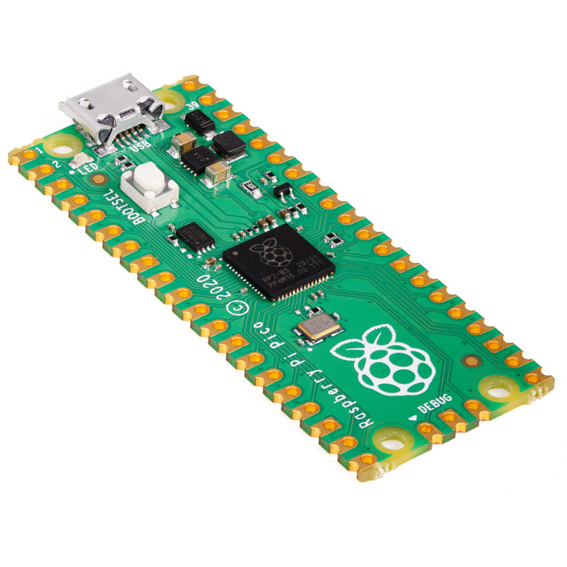
On the 21st of January, 2021, the Raspberry Pi Foundation released its own microcontroller board called the Raspberry Pi Pico. Despite its name, the Pico is a microcontroller, not a small microcomputer (i.e., a Single Board Computer or SBC) like the Raspberry Pi, uses a different CPU chipset (the RP2040, a proprietary design by the Raspberry Pi Foundation), and is significantly smaller and cheaper than any Pi at US$4.
It comes with a C SDK, a GCC-based toolchain, Visual Studio Code integration, and can be programmed in Micropython. The RP2040 CPU is currently available in the Pico form factor as released by the Raspberry Pi Foundation, but announcements have been made by many vendors like Adafruit and Pimoroni for Feather, Itsy Bitsy, QT, Tiny, and other familiar designs.
Specification#
 |
- 21 mm × 51 mm form factor
- RP2040 microcontroller chip designed by Raspberry Pi in the UK
- Dual-core Arm Cortex-M0+ processor, flexible clock running up to 133 MHz
- 264KB on-chip SRAM
- 2MB on-board QSPI Flash
- 26 multifunction GPIO pins, including 3 analogue inputs
- 2 × UART, 2 × SPI controllers, 2 × I2C controllers, 16 × PWM channels
- 1 × USB 1.1 controller and PHY, with host and device support
- 8 × Programmable I/O (PIO) state machines for custom peripheral support
- Supported input power 1.8–5.5V DC
- Operating temperature -20°C to +85°C
- Castellated module allows soldering direct to carrier boards
- Drag-and-drop programming using mass storage over USB
- Low-power sleep and dormant modes
- Accurate on-chip clock
- Temperature sensor
- Accelerated integer and floating-point libraries on-chip
From the Pico release announcement :
:
And this isn’t just a powerful chip: it’s designed to help you bring every last drop of that power to bear. With six independent banks of RAM, and a fully connected switch at the heart of its bus fabric, you can easily arrange for the cores and DMA engines to run in parallel without contention.
For power users, we provide a complete C SDK, a GCC-based toolchain, and Visual Studio Code integration.
As Cortex-M0+ lacks a floating-point unit, we have commissioned optimised floating-point functions from Mark Owen, author of the popular Qfplib libraries; these are substantially faster than their GCC library equivalents, and are licensed for use on any RP2040-based product.
With two fast cores and and a large amount of on-chip RAM, RP2040 is a great platform for machine learning applications. You can find Pete Warden’s port of Google’s TensorFlow Lite framework here. Look out for more machine learning content over the coming months.
For beginners, and other users who prefer high-level languages, we’ve worked with Damien George, creator of MicroPython, to build a polished port for RP2040; it exposes all of the chip’s hardware features, including our innovative PIO subsystem. And our friend Aivar Annamaa has added RP2040 MicroPython support to the popular
Thonny IDE.
Pinout#
 |
I2C #
The RP2040 has two I2C controllers (0 and 1), both accessible via the Pico's GPIO pins, where the selection of SDA and SDL pins used for each controller is configured in software as per the following table:
| I2C Controller | GPIO Pins |
|---|---|
| I2C0 – SDA | GP0/GP4/GP8/GP12/GP16/GP20 |
| I2C0 – SCL | GP1/GP5/GP9/GP13/GP17/GP21 |
| I2C1 – SDA | GP2/GP6/GP10/GP14/GP18/GP26 |
| I2C1 – SCL | GP3/GP7/GP11/GP15/GP19/GP27 |
The I2C controller can run in master or slave mode (default slave address is 0x55); a choice of three speeds: Standard (0-100kB/s), Fast (up to 400kB/s) and Fast Plus (<=1000kB/s). The Raspberry Pi's default I2C frequency is 100kB/s, unless altered in /boot/config.txt. It can be used in either interrupt or DMA mode and includes transmit and receive buffers to
improve performance. There are some I2C examples in Micropython on github.
Example Code#
The first block sets the SDA and SCL pins for I2C Controller 0 to pin 8 and 9 (resp.), then writes 3 bytes of data to the slave address 76, then reads 4 bytes back from the same address. The second configures I2C Controller 1 to pin 6 and 7, then writes 3 bytes to memory address starting at 6, then reads 4 bytes starting at address 2 of the slave at memory address 76.
  from machine import Pin, I2C

  i2c = I2C(0, scl=Pin(9), sda=Pin(8), freq=100000)
  i2c.scan()                        # scan for slaves, returning a list of 7-bit addresses

  i2c.writeto(42, b'123')           # write 3 bytes to slave with 7-bit address 42
  i2c.readfrom(42, 4)               # read 4 bytes from slave with 7-bit address 42

  i2c = I2C(1, scl=Pin(7), sda=Pin(6), freq=100000)
  i2c.scan()
  i2c.readfrom_mem(42, 8, 3)        # read 3 bytes from memory of slave 42,
                                    #   starting at memory-address 8 in the slave
  i2c.writeto_mem(42, 2, b'\x10')   # write 1 byte to memory of slave 42
                                    #   starting at address 2 in the slave
For further information consult the documentation for the Micropython machine library for I2C, or the C++ API. Note that I2C can be established either via hardware or software on the Pico.
Links#
- From Raspberry Pi Foundation:
- Meet Raspberry Silicon: Raspberry Pi Pico now on sale at $4 (release announcement)
- Pico Specification
- Getting Started
- Pico Product Brief
- RP2040 Datasheet (4.9MB PDF)
- Meet Raspberry Silicon: Raspberry Pi Pico now on sale at $4
- local documentation copies
- Raspberry Pi Pico Python SDK
 (2.8MB PDF, local copy)
- Getting Started with Raspberry Pi Pico (34.6MB PDF, local copy)
- Hardware design with RP2040 (19.7MB PDF, local copy)
- Raspberry Pi Pico Python SDK
- Pico Micropython Examples on github (adc, blink, i2c, irq, multicore, pio, pwm, spi, uart/loopback)
- RP2040 on Wikipedia
- An Introduction to the Raspberry Pi Pico with MicroPython, MakerPortal blog post by Joshua Hrisko, 28 Jan 2021