 |
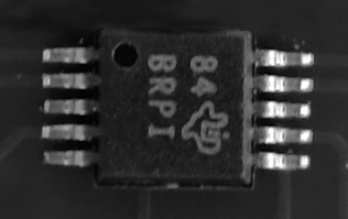
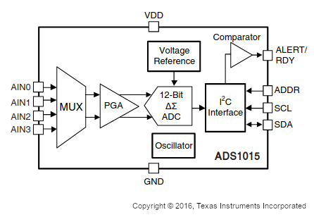
The Texas Instruments ADS1015 +/-24V Analog Digital Converter is a 2 x 1.5mm integrated circuit implemented by both AdaFruit and Pimoroni as I2C-compatible breakout boards (Pimoroni's is a "Breakout Garden" board). It can be used to measure analog voltage sources between -24V DC to +24V DC at sampling rates up to 3.3kHz, returning a value with 12 bit precision.
The ADS1015 has four channels (labeled A0, A1, A2 and A3). The Pimoroni board only provides three of these channels as usable pins.
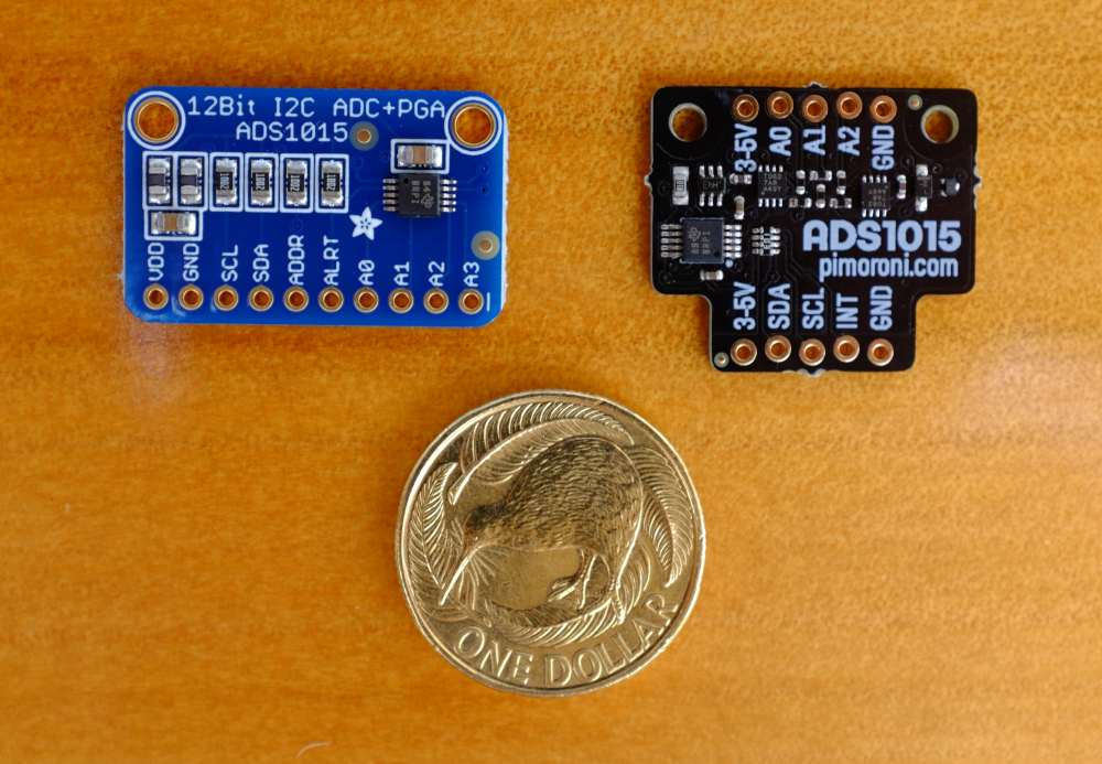 |
The thumbnail image to the right is roughly the size of the Adafruit and Pimoroni boards, which measure 28 x 17mm and 24 x 21mm respectively.
As of January 2020 the price of the AdaFruit board is US$9 (~NZ$14), also available from DigiKey NZ at NZ$16.57 (where shipping is free if you order over NZ$66). The price of the Pimoroni board is £12 (~NZ$24).
Features#
 |
- 12-bit precision (Adafruit also sell a 16-bit version, see ADS1115
 )
)
- +/- 24V (DC) measurement range
- the TI ADS1015 has four channels: AdaFruit's provides all four, whereas Pimoroni's board only provides connections to three of them
- programmable gain (please consult the ADS1015 TI datasheet for details; the default is set at ±2.048V)
- pp to 3.3KHz sampling rate
- I2C interface: the Pimoroni board uses address 0x48 or 0x49 with a cut trace; the Adafruit board can be programmed for up to 4 different addresses)
- 3.3V or 5V compatible
- reverse polarity protection
Both boards are compatible with all models of Raspberry Pi and Arduino, depending on which software libraries you intend to use.
Installation#
The Adafruit board has its own installation page (which we won't repeat here, see References below).
For the Pimoroni board, Python and pip (or pip3 for Python 3) must be installed.
Then, if you're using Python 2, just run:
sudo pip install ads1015or for Python 3:
sudo pip3 install ads1015
Example Usage#
The board has three input pins, labeled A0, A1 and A2. Plugging a signal into A0, here's an example of some code to repeatedly read the voltage on the pin until you type Ctrl-C:
    #!/usr/bin/env python3
    import time
    from ads1015 import ADS1015

    print('''read-all.py - read the A0 input of the ADC.

    Press Ctrl+C to exit!
    ''')

    CHANNEL = 'in0/ref'
    ads1015 = ADS1015()
    ads1015.set_mode('single')
    ads1015.set_programmable_gain(2.048)
    ads1015.set_sample_rate(1600)

    reference = ads1015.get_reference_voltage()
    print("Reference voltage: {:6.3f}v \n".format(reference))

    try:
        while True:
            value = ads1015.get_compensated_voltage(channel=CHANNEL, reference_voltage=reference)
            print("A0 value: {:6.3f}v".format(value))
            time.sleep(0.5)

    except KeyboardInterrupt:
        pass
References#
- ADS1015 12-Bit ADC - 4 Channel with Programmable Gain Amplifier Adafruit product page
- ADS1015 +/-24V ADC breakout Pimoroni product page
- ads1015-python library on github
- ads1015-python library
- Adafruit ADS1015 product page on DigiKey
- ADS101x Ultra-Small, Low-Power, I2C-Compatible, 3.3-kSPS, 12-Bit ADCs With Internal Reference, Oscillator, and Programmable Comparator datasheet from Texas Instruments